Honda CB Carburetor Rebuild
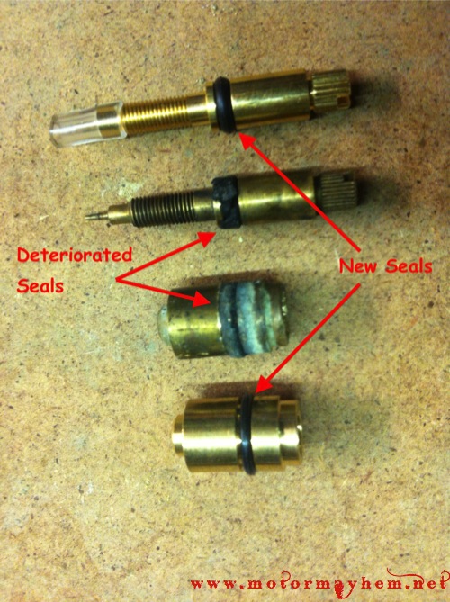 Rebuilding the Keihin CV carburetors on your Honda CB/CJ/CL 360 goes a long way towards making it run like a well oiled machine. With age and lack of use, varnish builds up causing the jets and small passages in the carburetor to become plugged while seals deteriorate causing air and fuel leaks. Disassembling, cleaning, and rebuilding the carburetors is a pretty simple process that can be completed in a matter of hours with just a handful of tools.
When you might need a rebuild:
- Fuel leaking from the carburetor throat or overflow tube when sitting (leaking float valve / seat seal
- Trouble idling / idle adjustment screw unresponsive (idle circuit plugged / idle needle seals bad)
- Engine running rough / popping (plugged jets or emulsifier tubes)
Where to buy rebuild kits:
Common motor collective sells all the parts needed to restore your carburetors to top working condition. Here are direct links to the parts you might need.
The Rebuild Process:
Disassembly:
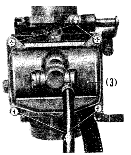
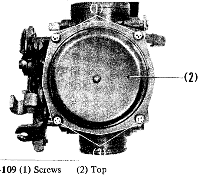
Once the carburetors have been removed from the bike, the disassembly process can begin. First, remove the diaphragm cover and fuel bowl from the carburetors. (shown to the right)
With the diaphragm cover removed, carefully remove the slides and diaphragms from the main body. Be careful to not tear the diaphragms when removing them from the main body. Apply some penetrating oil to the groove the diaphragm sits in and let it soak. Then carefully work the diaphragm out of the groove with a dull pick.
Note:
- If replacing the slide diaphragms, follow these instructions included with the new diaphragms for replacement.
With the fuel bowl and slide / diaphragm assembly removed, you will have full access to the passages and jets inside the carburetor.
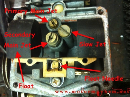
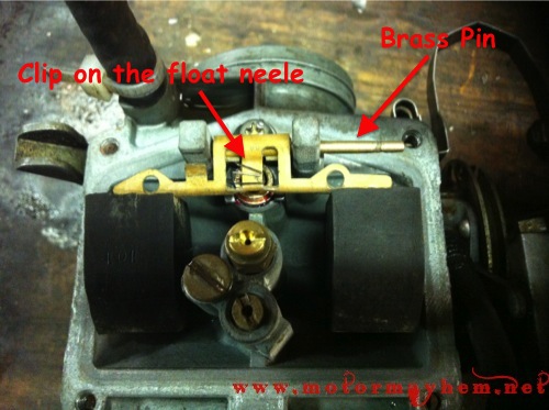
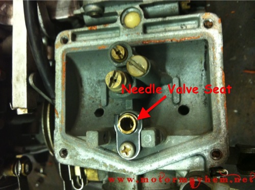
The first step in disassembly is to remove the float and attached needle. This is done by sliding the brass pin out from the float pivot. This pin is retained by the fuel bowl removed earlier. The pin will just slide out, allowing the float and needle to be removed and the needle valve seat to be exposed.
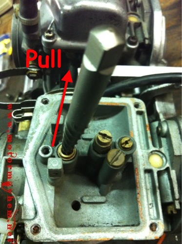
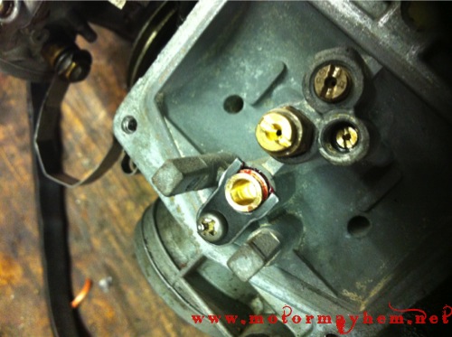
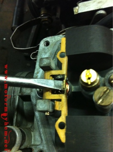
With the float and needle valve assembly removed, the needle valve seat can be removed for replacement. The seat is held in place by a screw and retaining tab that should be removed. I use an extractor bit to pull the seat, however, a set of needle nose pliers should work fine as well. With the tab removed, the seat can simply be pulled straight out. If the seat is stuck, rotating the seat while pulling it helps break the bond between the carburetor body and seat o-ring.
With the seat removed, inspect the seat sealing surface in the main body of the carburetor housing for damage and debris that could cut or otherwise prevent the new o-ring from sealing.
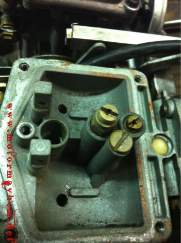
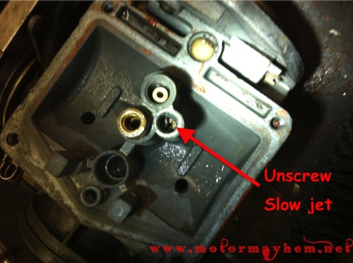
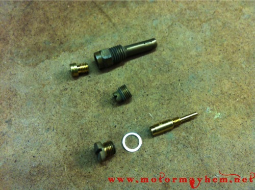
It is now time to remove the jets from the carburetor body. This is done by unscrewing each brass jet. Be careful when removing the jets, as brass is soft and can strip easily. In order to remove the slow jet, remove the screw above it and use a small flat head screwdriver to unscrew the jet. With the jets removed, unscrew the main needle jet holder with an 8mm socket.
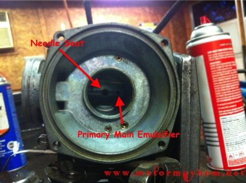
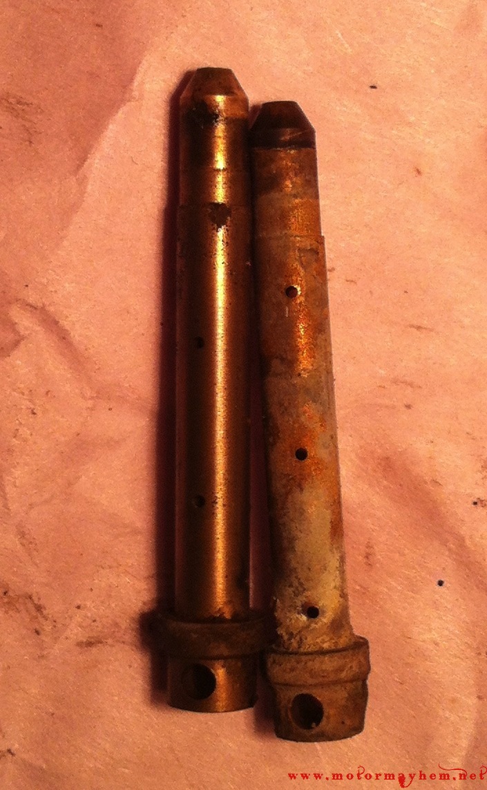
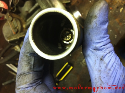
With all the jets removed, the needle seat and primary main emulsifier can be pressed out of the carburetor body. This is best done using a wooden dowel or chopstick inserted through the top of the carburetor (where the slide sits) and lightly taping them out.
As you can see, on my right carburetor there was a lot of debris plugging the primary main emulsifier tube which was causing my cb 360 to run rich and sputter when in the 1/8 – 1/4 throttle range.
Float and Jet Rebuild:
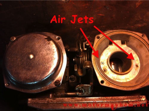
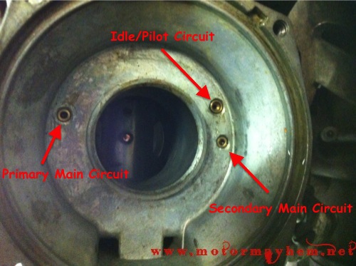
 Once everything is removed from the carburetor body it is time to clean the passages inside the carburetor body. The easiest way to do this is by using carb and choke cleaner and air to blow out the passages and air jets in the carburetor. The passages to clean are detailed below.
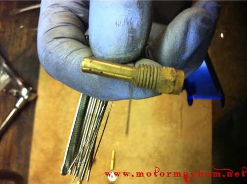
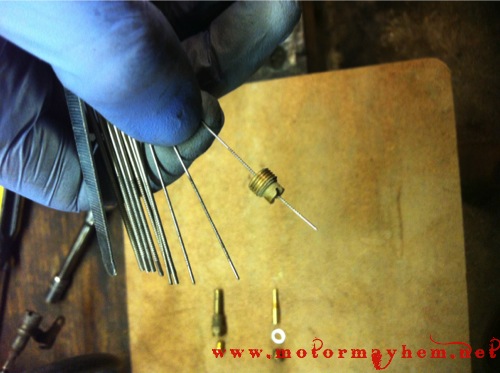
To clean the emulsifier tubes and jets use an apropriate size drill bit (metric) or copper wire and carb and choke cleaner to clear and blow clean all the holes. Be careful to not alter the size of any of the holes in the jets, passages, or emulsifier tubes by forcing too large of a cleaner though the brass as it is very soft.
In a bind I have also used a torch tip cleaner tool, using a size 1-2 sizes smaller than the diameter of the hole your trying to clean. This will help prevent you from accidentally filing the edges of the hole. A torch cleaner tool is likely to damage the jets unless you are very carfeful so the two methods mentioned above should be your first choice. Clean the primary main jet for reuse if a new jet was not included in your rebuild kit. Clean and re-use the pilot jet.
Clean the passages connecting the air jets and to the fuel jets/emulsifier tubes shown below. I used compressed air and carb and choke cleaner to blow these passages clean. It is important to make sure these passages are clean as the carburetors will not fuel correctly when they are blocked.
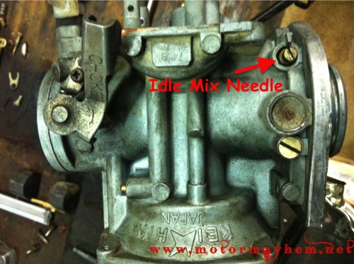
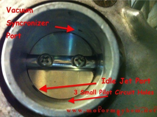
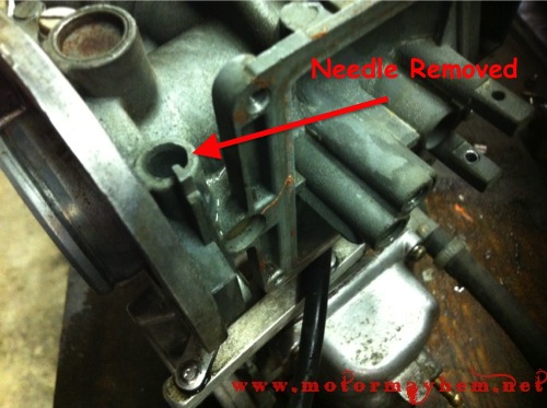
In order to clean the idle circuit, remove the idle adjustment screw. Blow the passage between the carburetor throat and idle adjustment screw clean (Idle Jet Port & 3 small Pilot Circuit Holes) as well as the passage between the idle adjustment screw and idle jet as shown below. With those passages clean, install the new idle adjustment needle with o-ring.
With all the jets and passages now clean, it is time to install the new jets. First, install the needle seat and primary main emulsifier tube pressed out earlier. Then, screw the new or cleaned jets into their respective holes in the carburetor body.
Note:
- When screwing the secondary main emulsifier tube back into the body, ensure the secondary main jets in both carburetors are screwed in the same amount. This will allow the height of the secondary main jets relative to the fuel level in bowl to be the same and help with synchronization.
- Ensure both emulsifier tubes are snugged against the needle seat.
Install the new float seat by pressing it into the carburetor body. Apply a small film of grease around the o-ring on the seat before installing to allow it to slide in easier and prevent damage to the o-ring. Be sure to wipe any residual grease off to prevent it from plugging any passages later on.
Note:
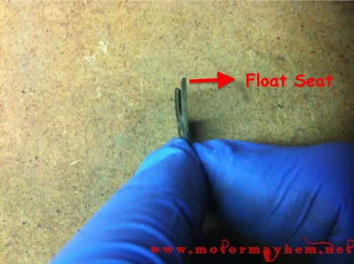
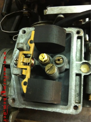
- The float seat retaining clip has a slight bend to it. Orient this so the bend is pushing down the seat when the screw is tightened as shown in the picture.
With the everything else reinstalled into the carburetor it is time to install the float and float needle. Slide the clip on the float needle over the tang on the float and install the float/needle assembly into the carburetor using the brass pin again.
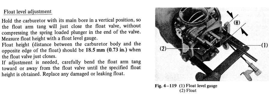
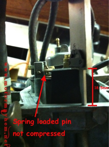
Now it is time to adjust the float height. The stock float height is 18.5 mm but with my current setup I have found 19.5 mm works better. I was having trouble with the bike running rich a low speed. Others have found that 16 mm – 16.5 mm works better if they are having trouble with the bike leaning out after high rpm operation. Therefore it may take some adjustment to figure out what works best for your bike.
Remember fuel level height and float height are inversely related. A lower float height, 16mm, means more fuel in the bowel. A higher float height, 19mm, means less fuel in the bowl.
I recommend starting with the stock setting and adjusting from there if you have issues. Also be aware if you set the fuel level too high (lower float height) fuel may drain out the overflow tubes in the carburetor when the bike is sitting.
Here is the factory float height adjustment procedure:
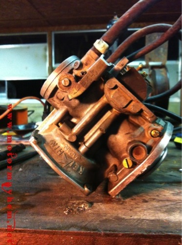
If you do not have at float level gauge a pair of calipers can be used to check the float level. Orient the carburetor as shown in the first picture below to allow the float to lightly rest on the spling loaded pin of the float needle without compressing it and carefully measure the max height of the float from the flat surface where the fuel bowl seals. If the float is too low, use a small flathead screwdriver to bend the tang to increase the height. If the height is too high, remove the float and needle and use a pair of needle nose pliers to bend the tang then re-install.
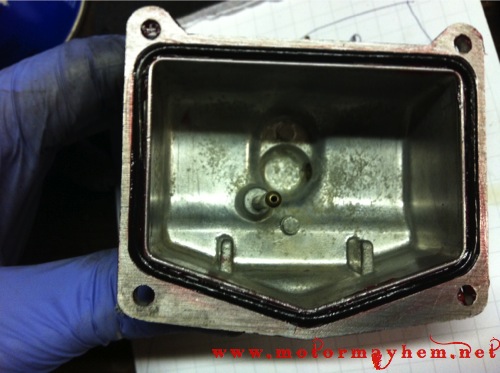
Assembly of the bottom end of the carburetor is now complete. Reinstall the fuel bowl using the new o ring that came with your rebuild kit. I use a small amount of grease to retain the o ring in the groove.
Slide Reinstallation:
With the bottom end of the carburetor assembled, it is now time to take care of the slides.
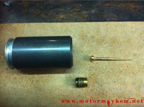
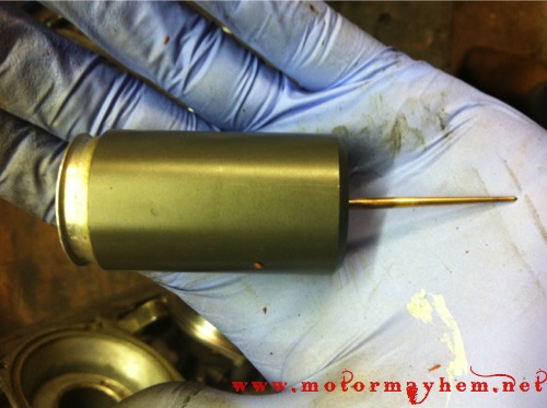
If your rebuild kit came with new needles, remove the screw inside the slide and push the needle out. Install the new needle and replace the screw. The needle should have some “wobble” to it when installed correctly to prevent the slide from binding.
***If replacing the slide diaphragms, follow these instructions included with the new diaphragms for replacement.
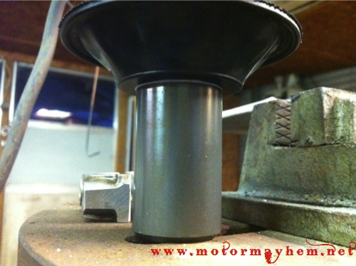
With the slides reassembled, install them back to the carburetor ensuring the holes in the slide are aligned away from the engine side of the carburetor, parallel to the intake of the carburetor. Carefully press the diaphragm lip back into the groove on the top of the carburetor and reinstall the cover plate.
Carburetor Bench Synchronization:
If you don’t have the fittings and gauges to properly sync the carburetors on the engine, it is necessary to bench sync the carburetors to get the bike in somewhat running condition (even after bench syncing you will have to fine tune sync on the engine). If you are planning to sync the carburetors on the engine it is still a good idea to bench sync the carburetors to get them close to adjustment before installing.
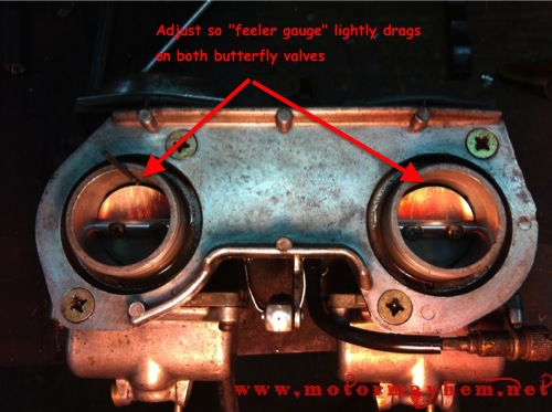
Bench syncing the carburetor is very simple. Using a piece of wire or a small drill bit adjust the sync screw between the carburetors so at idle the butterfly valves are open exactly the same amount. The sync screw is located between the two carburetor bodies and is show in the drawing below. While preforming a bench sync, ensure the throttle plates (round disk that rotates in the carburetor throat) are centered in the carburetor body. You may need to loosen the two screws that hold each one on the throttle shaft and close the throttle to allow it to center before tightening the screws again. Ensure the opening below/to the sides of the throttle plates are even and they can close completely without binding on the sides of the carburetor.
You can measure this opening with a cylindrical feeler gauge, piece of wire, or small drill bit. If you don’t have a piece of wire small enough, try turning the idle adjustment screw all the way up to uniformly open both butterfly valves as much as possible and then adjust the sync. Be careful no to over torque the jam nut on the sync screw as it does not need to be tighter than 1/8 turn past finger tight.
With the sync done the carburetors are now ready to be reinstalled onto the bike. Fine tuning of the synchronization and idle adjustments will need to be made with the bike running.
The simplest (not as good as syncing the gauges but will get you close) way to fine tune the sync is to set the idle around 2000rpm and pull one of the plug wires and see where the bike idles. Reinstall that plug wire and pull the other plug wire and compare the two idle speeds. Then adjust the sync screw until it idles at the same speed no matter what plug wire is pulled.
Adjusting the idle mixture screws is also pretty easy on the bike. With the bike sitting at ride height and 1200rpm idle, adjust the idle screw on one carburetor to achieve the highest idle speed. Turn the main idle speed screw back down to 1200 rpm and continue adjusting alternating between both carburetors and re-adjusting the main idle speed screw back to 1200rpm each time until both screws are set to the position that gives the highest idle. 2.5 turns out from just snugged closed should get you close. Be sure to re-adjust the main idle speed screw to 1200 each time before continuing adjustment.
***Please provide feedback in the comments below so we can be sure to improve and provide more information like this in the future***


[…] […]
Family Chiropractic Culver City
Motor Mayhem » Blog Archive » Honda CB Carburetor Rebuild
I wanted to thank you for having this posted, it was very helpful in rebuilding a set of 1976 CL360 carburetors. we also used it to bench sync the carbs.
[…] […]
[…] […]
[…] […]
[…] […]
This sit helped me though the whole rebuild.it’s so detailed it takes you step by step
[…] […]
[…] […]
I havent had a problem with the torch cleaners but I can see where you could easily cause problems with them. Re-worded that section to make it a little more clear about the dangers.
Oh, almost forgot, you need to check throttle plates are centered in carb bore, may need to loosen screws to get things right
Thanks for the input! I forgot I ran into that very issue a few months before rebuilding the carburetors completely. I’ll add that step in
Pretty good guid except for the gas torch reamers. Tey are too big to clean pilot jet and will enlarge the the fuel or air jets. I use correct size metric drills to clean precision sized holes
crazypj, looking to purchase your starter plug and speedo spacer. I just purchased a 1976 cb360T basket case and want to lose a few pounds.
thanks
roger.
How do I contact you?
I have a 1975 Honda cb 360 t . Would you be able to rebuild them for me? THANK YOU . LEW M.